When the model is solved there are results spreadsheets
The general wall detail report shows the material type, height, length, and envelope forces for general walls.
Note
The Wall Results Spreadsheet displays the calculated results for wall elements and may be accessed by selecting Wall Results on the Results menu. The spreadsheet has three tabs: Masonry Wall, Masonry Lintel, and Wood Wall.
The results displayed on this tab are explained below.
![]()
The Wall Panel column displays the wall panel label.
The Region column displays the region label.
The Axial UC column displays the axial force code check.
The LC column reports the governing Load Combination.
The Pn*Phi column reports the allowable axial force for the reported Region on a per foot basis.
The results displayed on this tab are explained below.
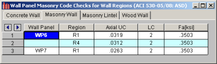
The Wall Panel column displays the wall panel label.
The Region column displays the region label.
The Axial UC column displays the axial force code check.
The LC column reports the governing Load Combination.
The Fa column reports the allowable axial force for the reported Region.
The Masonry Lintel tab displays the various code checks and their associated load cases as well as the allowable forces. The results displayed on this tab are explained below.
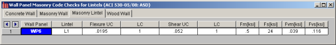
The WallPanel column displays the wall panel label.
The Lintel column displays the lintel label.
The Flexure UC column reports the flexural code check for the lintel.
The Shear UC column reports the shear code check for the lintel.
The LC columns following the Flexure LC and the Shear LC report the governing load combinations for each of those checks.
The Fm column displays the allowable compressive stress of the masonry.
The Fs column displays the allowable tensile or compressive stress of the reinforcing steel.
The Fvm column displays the allowable shear stress of the masonry.
The Fvs column displays the allowable shear stress of the reinforcing steel.
The Wood Wall tab displays the various code checks and their associated load cases as well for the studs and the chords. The results displayed on this tab are explained below.
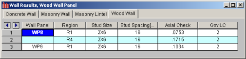
The Region column reports which region the results are being shown for. See the notes below for more information.
The Stud Sizereports the studs for the designed wall.
The Stud Spacing displays the spacing for the designed studs.
The Axial Check reports the code checks for the wood wall.
The Gov LC reports the governing load combinations for the code checks.
Note:
![]()
The Header Label gives the label of your header. If there is more than one header in a wall you can see which is which in the wall panel editor.
The Design Rule gives the rule that is defining the size and material.
The Size gives the size from the Design Rule.
The Bend UC value is a bending code check ratio. This is given for the load combination from the Gov LC column.
The Shear UC value is a shear code check ratio. This is given for the load combination from the Gov LC column.
The Gov LC gives the load combination that governed the design. The program finds the largest UC value for either bending or shear and reports the associated load combination here.
Note:
The Wall Forces Spreadsheet displays the calculated results for wall panel elements and may be accessed by selecting Wall Results on the Results menu. The spreadsheet has three tabs: Dead & Other, Floor Live Load, and Roof Load.
The Dead & Other tab displays the axial forces in the wall due to dead and other load categories. The results displayed on this tab are explained below.
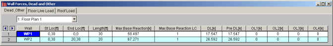
The Wall column displays the wall label.
The St Loc and End Loc columns display the plan coordinates for the starting and ending points of each wall.
The Length column displays the length of the wall.
The Max Base Reaction and Max Base Reaction LC columns display the maximum base reaction and its governing load combination.
PreDL and DL give the total axial forces in the wall due to the dead load categories.
The OL1, OL2, OL3, and OL4 columns give the total axial force in the wall due to the 'Other' load categories.
The Floor Live Load tab displays the location and live load reduction information for each wall panel. The results displayed on this tab are explained below.
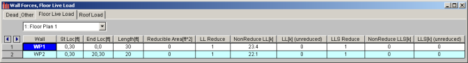
The St Loc and End Loc columns display the plan coordinates for the starting and ending points of each wall.
The Length column displays the length of the wall.
The Reducible Area column lists the total tributary area to be considered for live load reduction for each wall.
The LL Reduce and LLS Reduce columns display the live load reduction factors for the various live load categories.
The NonReduce LL columns give the total axial force in the wall due to the non-reducible live load cases. The included load cases are LL and LLS.
The LL Unreduced columns give the total unreduced axial forces in the wall due to the reducible live load cases. The included load cases are LL-Reduce and LLS-Reduce. It is important to note that the forces listed in this column have not been reduced by the load reduction factors.
The Roof Load tab displays the location and roof live load reduction information for each wall panel. The results displayed on this tab are explained below.
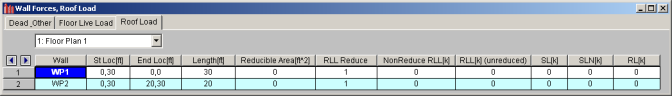
The St Loc and End Loc columns display the plan coordinates for the starting and ending points of each wall.
The Length column displays the length of the wall.
The Reducible Area column lists the total tributary area to be considered for live load reduction for each wall.
The RLL Reduce column displays the live load reduction factor.
The NonReduce RLL column gives the total axial force in the wall due to the non-reducible roof live load case.
The RLL Unreduced column gives the total unreduced axial forces in the wall due to the reducible roof live load cases. It is important to note that the forces listed in this column have not been reduced by the load reduction factors
The SL, SLN, and RL columns display the total axial force in the wall due to these load cases.